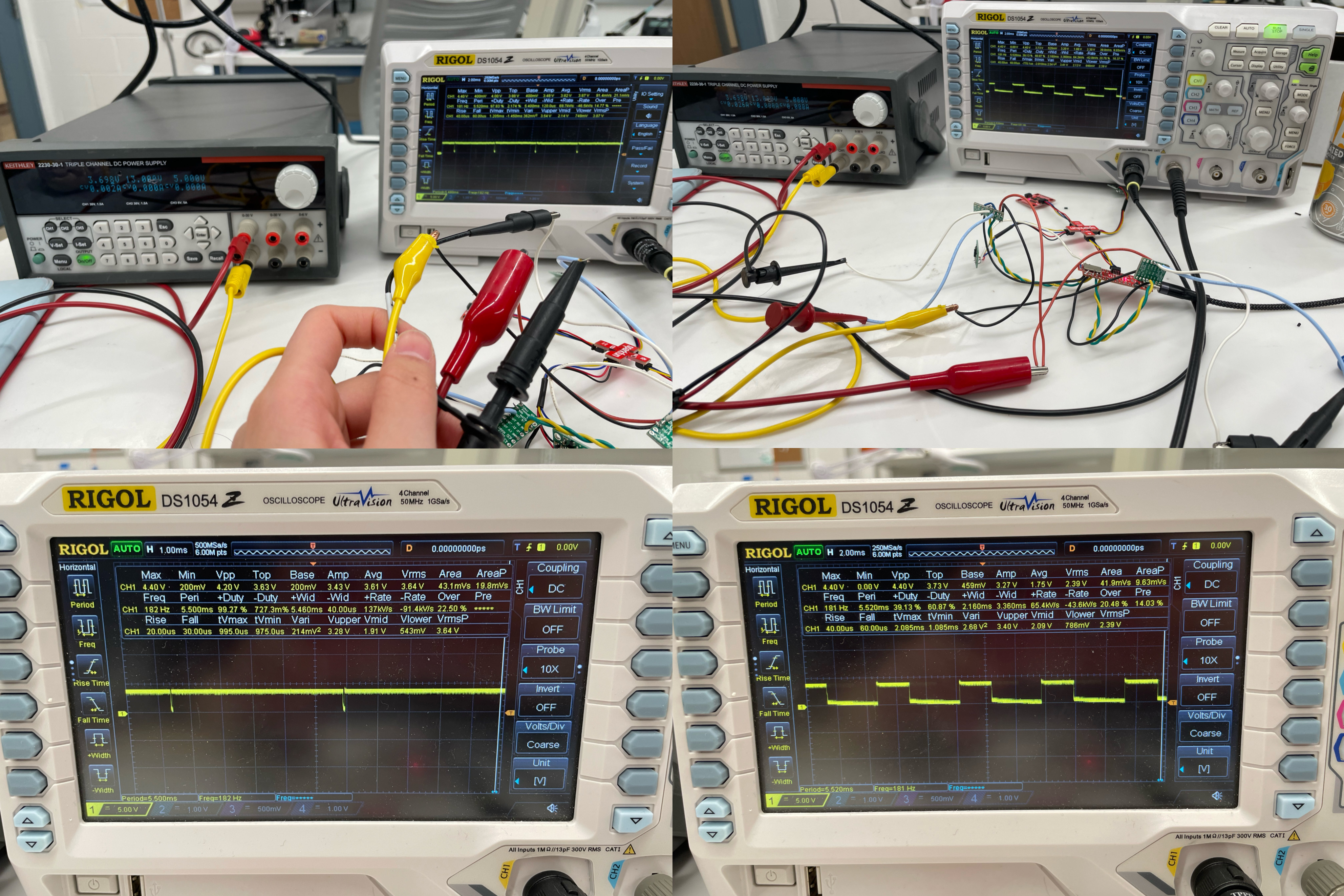
Scoping PWM signal
The first task in this lab was to solder the two DRV8833 dual motor drivers to the Artemis board. This
was a bit challenging since we are using the dual motor driver to control a single motor each, meaning I needed to
solder the AIN1 and BIN1, AIN2 and BIN2, AOUT1 ane BOUT1, and AOUT2 and BOUT2 pins together. I did this by soldering
a wire to partially stick through the board's hole and then bending it around to solder it to the corresponding A/B
pin. To check my soldering connections and also verify the functionality of the drivers, I sent a PWM signal from
the Artemis board and scoped the output of the drivers. I sent a PWM of 100 (roughly 50% duty cycle) and also 253 (almost
100% duty cycle, but still has a dip to differentiate it from zero) using the following code where pwm is an int variable:
analogWrite(6, pwm);
analogWrite(7, 0);
Here are photos of the scope setup, where the driver is powered
by a 3.7V power supply to emulate the 3.7V battery used in the robot, as well as the displayed oscilloscope results: